|
|
|
ISDN Telecommunications Network
WHAT IS ISDN
ISDN is a network architecture in which digital technology is used to convey information from multiple networks to the end user. This information is end-to-end digital. There are two forms of ISDN service.
You can have a single ISDN line installed, just like a conventional phone line, but you can use it for any/all of the following purposes:
Ø High speed computer to computer data communication. Ø Computer based video conferencing, ISDN caller identity phone , video phone, document camera ,etc. Ø Eight times faster fax transmission Ø High quality voice communication.
Narrowband ISDN
Narrowband ISDN is digital service where the transport speeds are 1.544Mbs (T1) or less. Narrowband ISDN provides for the following services.
Circuit Switched Voice
Circuit switched voice service is a digital voice service that offers many of the capabilities of a business Centrex over a 4-wire ISDN Digital Subscriber Line (DSL).
Circuit Switched Data
Circuit switched data service provides end-to-end digital service to pass data or video information over the public network. ISDN uses out-of-band signaling to establish and maintain data connections, which require special processing.
Low Speed Packet
ISDN lines are equipped with a packet connection which is used to manage ISDN connections. This monitoring capability is provided by using the D channel on a DSL. The D channel is a 16Kbs X.25 connection that is also capable of passing low speed packet while also relaying call-processing information.
High Speed Packet
ISDN lines are also equipped with two B channels. Each B channel is a 64Kbs channel that can be used for circuit switched voice; circuit switched data, or high speed packet service. To provision high speed packet service one or both of the 64Kbs B channels are nailed up (permanent virtual circuit) to the packet network thus providing a 64Kbs X.25 connection.
Broadband ISDN Service
Broadband ISDN Service is digital service in excess of 1.544Mbs. This digital service can be in the form of Frame Relay, SMDS, or ATM. Broadband ISDN is the service of the future. The higher speeds offered are required to support the many applications of the Information Super Highway. The range of speeds for the Broadband ISDN services usually range from 25Mbs up to the Gigabit range. The two speeds that are most often discussed are OC 1 which is 155Mbs and OC 3 which is 622Mbs. The speeds in the Broadband are made possible by the high quality of the digital facilities in place on the network. The early data protocols such as X.25 required extensive overhead to insure the delivery of data. Error correction and flow control were performed at a number of intermittent points along the way of a data connection. The new digital facilities and the introduction of fiber optics has all but eliminated this need. High speed broadband services rely for the most part on the upper layer protocols to perform these functions on an end-to-end basis.
Frame Relay
Frame Relay service is a service that supports the transport of data. Frame relay is a connectionless service, meaning that each data packet passing through the network contains address information. Frame relay is a service that is provided with a variety of speeds from 56Kbs up to 25Mbs. Even though the most used speeds for the service are currently 56Kbs and 1.544Mbs Frame Relay is considered to be a Broadband ISDN service. One of the unique facets of frame relay service is that the service supports variable size data packets.
Switched Multimegabit Digital Service - SMDS
SMDS is a digital service that provides a high speed digital path for permanent virtual circuits. The transport speed for SMDS is usually 155 Mbs.
Asynchronous Transfer Mode - ATM
ATM which is also known as cell relay is considered by most to be the transport service of the future. The transport speeds of most ATM applications are most often 155Mbs with the promise of 622 Mbs. in the near future. ATM is a flexible service made possible by the size of the packets (cells). The cell size for all applications is 53 bytes. The small cell size allows a variety of applications to run on ATM networks including voice, video, and data. The appeal of the service has to do with the ability to pass voice and video information. These two services are time sensitive or otherwise known as isochronous data. This means that voice and video are susceptible to time delays. The small cell size of ATM and the service options such as Continuous Bit Rate Service allow such traffic to flow over the network where others such as Frame Relay and SMDS can not guarantee this level of service.
TYPES OF CONNECTION
Basic Rate Interface
ISDN Basic Rate Interface Service defines digital service to the user. That is the connection from the ISDN office to the user location provides for access to three channels. The channels are two 64Kb B-channels and one 16Kb D-channel.The B-channels and the D-channel provide the user with access to the circuit switched network (this is the telephone network we are familiar with) and also provides access to the X.25 packet network. The channels can be provisioned as follows.
B1 - Voice, Data, B channel Packet (high speed 64Kb) B2 - Voice, Data, B Channel Packet (high speed 64Kb) D - Signaling, D Channel Packet (low speed 16Kb)Primary Rate Interface
ISDN Primary Rate Interface service provides digital access via a T1 line. A T1 line provides a 1.544 bandwidth. This bandwidth is divided into 24 64Kb channels. The ISDN PRI service uses 23 of the T1 channels to provide B channel access and uses the 24th channel for signaling purposes. ISDN call control procedures use packetized messages to initiate, monitor, and release connections. In a BRI call these messages are routed via the D channel. On the PRI service the call control messages are routed over the 24th channel which is the D channel in this instance.OSI Reference Model
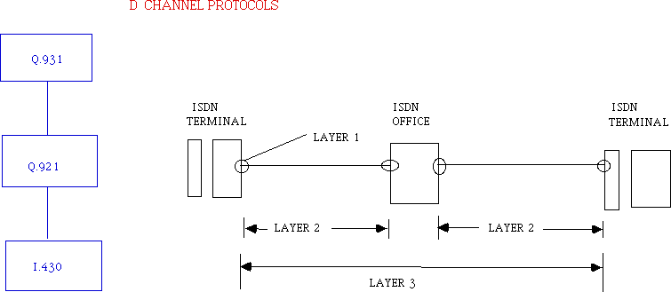
The standards used to define ISDN, (both Custom and National), make use of the OSI reference model. This is simply a generic standard of how protocols are defined. This modular approach allows work to be performed on various levels of the model knowing what is required from the lower level and the requirements of the next higher level. In ISDN we are concerned with the first three layers of this OSI reference model.

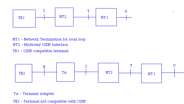
Physical Layer The physical layer of the OSI model defines the physical properties of an ISDN circuit. Examples of such are; the connector type, how many leads in a cable, what is on pin 1..pin 8 etc, what defines a pulse..is it 1 volt or is it a range from .75 volts to 1.18 volts. All of these parameters make up the Layer 1 specifics of the ISDN line. The technical specifics are contained in the CCITT (ITU-T) documents. The specification for a Basic Rate Interface is document I.430 and for the Primary Rate Interface it is document I.431. In order to specify the electrical standard there has to be agreement on where to measure these requirements. This has resulted in the definition of user/network interfaces. The interfaces for an ISDN Basic Rate Interface are as follows;
ISDN Physical Interfaces

Definitions
U interface - The U interface is particular to the US. The U interface is necessary due to the on average longer local loop lengths in the US. In such a case where the local loop length exceeds approximately 3,300 ft (1 kilometer) of 22 gauge wire the strength of the signal must be increased. The older AT&T proprietary version was to use alternate mark inversion (AMI) line code. The current standard is the American National Standards Institute (ANSI) 2B1Q line code. The line code groups two bits together and codes them in voltage levels of +3, +1, -1, -3 volts.
NT1 Unit - The NT1 unit is the component on the user's side of an ISDN U line. The purpose of the NT1 is to convert the incoming line code from AMI or 2B1Q to bipolar. The NT1 also provides the demarcation between the public telco network and the customer equipment. There is digital loop back capability in the unit for testing purposes. The NT1 device is owned by the customer. The output of the NT1 is the T interface.
NT2 - The NT2 is a device which provides multiple ISDN interfaces on an ISDN line. The NT2 may be as simple as a bridging device connected to an NT1 unit or it may be as complicated as a PBX. The interface to the NT2 device is the T interface.
TE1 - The Terminal Equipment 1 is terminal equipment provided with an ISDN interface capability. This equipment will thus receive and process bipolar digital signals from the network. This equipment may be a computer, fax or a PCMIA. Note that the interface to this component is the S interface. Basically the S and T interface are electrically identical. The equipment may be served directly from the office if the loop length is short or may be a U line equipped with an NT1 which thus provides the S/T interface.
TA - The Terminal Adapter is the ISDN device that adapts non-ISDN equipment to work on an ISDN line. The purpose of the terminal adapter is to convert the bipolar signaling from the public network to the unipolar signaling used by computers. The most prevalent use for a terminal adapter is to connect a computer to an ISDN line.
TE2 - Terminal Equipment 2 is terminal equipment that does not have an ISDN interface. This equipment needs an ISDN terminal adapter to function on an ISDN line.
Connectors
The physical Layer also defines the type of connectors used. ISDN primarily uses three types of connectors.
RJ11 This is a 4 conductor telephone cord. This can be used to connect a U ISDN line to the line side of a power source. RJ12 This is a 6 conductor ISDN cord, This cord is used to connect from a power supply to the line side of the NT1 unit. RJ45 This is the 8 conductor cord used for ISDN.Layer 2 Q.921
The Q.921 recommendation defines layer 2 for ISDN lines. In the OSI reference model layer 2 provides for procedures established to maintain communication between two network components. In the case of ISDN the two components are the ISDN terminal and the ISDN switch. This means that ISDN terminals are in constant communication with the ISDN switch. An example of this is that when an ISDN terminal is plugged in a red led will illuminate. This led is an indication that layer 2 is established with the ISDN switch. Also notice that when a terminal is plugged in that the led does immediately light, it may take a minute or so. The reason for this delay is that there is negotiation between the terminal and the switch to reach agreement on the means of communication. Once there is agreement on the procedures then layer 2 connection is established and the red led will come on.
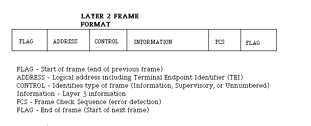
The procedures define the protocol to be used which is Q.921. Contained in the protocol specification defines the frame structure of the data packets, the procedure elements, the format of the fields in a frame and the procedures themselves known as Link Access Procedures - D Channel (LAPD). The LAPD procedures describe such things as flags, sequence control, flow control and re transmission.

Layer 3 Q.931
The Q.931 defines the layer 3 specifications for ISDN. Layer 3 as described by the OSI reference model defines the network layer. The network layer provides procedures to make end-to-end connections on the network. Remember that the ISDN connections established are for circuit switched voice and circuit switched data connections. Connections that involve X.25 packet conform to the X.25 protocol and different connection procedures.
Q.931 procedures used packetized messages to initiate, monitor and release circuit switched connections. Call procedure messages are relayed between the ISDN terminal and the ISDN switch as the "information" part of the Q.921 information frame. Each call control message has a number of mandatory information elements and optional elements. What is mandatory and what is optional depends on the circumstances of the message. If, however any mandatory information elements are missing the message will be rejected and the call abandoned. A typical message exchange follows.
LAYER 3 CALL CONTROL PROCEDURE
X.25 Protocols The X.25 protocol defines the layer 2 and layer 3 specifications for packet connections. The layer 2 connection is the data link layer. This specification defines the packet frame and connection procedures to establish and maintain a data link between two network components. An example of such a packet connection here at MIT would be an ISDN terminal connection to the 5ESS switch which may be used to establish a D channel X.25 connection to the modem pool. The packet frame follows the same format as the HDLC frame we have seen in Q.921 protocol specifications. The procedure as defined by the ITU-T (formerly the CCITT) is link access procedure-balanced - LAPB.
The X.25 layer 3 protocol defines the network procedures used to initiate, maintain, and release packet connections. Packet services can be divided into two categories or types of connections. The first type of X.25 service is "connectionless". This type of service is also known as datagram service. This type of packet service is where data packets are placed onto the network independently. That is, each packet has the necessary address and service information required to route the packet through the network to the destination node. In this type of connection packets may take a number of different routes to reach the correct address. Different routes may be required due to network congestion and/or link or component failures.
The second type of packet service is known as connection service. In this type of packet service connection information is retained until the completion of the desired connection session. All packets involved in the session are routed via the same nodes to the desired address location. This is the type of packet service provided with ISDN in the 5ESS switch.
The X.25 protocol defines procedures that were developed in the 70's. These procedures include provision for extensive error detection and data re- transmission. When the X.25 packet specification was developed in the 70's the state of the public network required such robust procedures. The present day public network is primarily a digital network and much less susceptible to data loss due to noise and link failure. The X.25 standard is thus slow. Many applications that have used X.25 in the past may now be more readily served via Frame Relay or ATM.
A typical X.25 message exchange to initiate a data session is as follows.
X.25 PACKET CONNECTION PROCEDURES
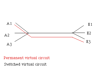
X.25 Connections There are two types of packet connections. The two types are Permanent Virtual Circuits and Switched Virtual Circuits.
Permanent Virtual Circuit A permanent virtual circuit is a connection which is permanently assigned. In the business we say that this circuit is "nailed up". On a permanent virtual circuit whenever I send information on the network it is always delivered to the same terminal. The address information for the data sent is always the same. For instance in the network below whenever I type onto terminal A1 the message is delivered to terminal E3. The circuit is "virtual" in that there is not a real hardwire connection between the two terminals but from the action of the connection it would seem so.
Switched Virtual Circuit A switched virtual circuit is a circuit where the information is delivered based on the address information provided on a session by session basis. In other words address information must be provided when a new session is initiated. In our example below terminal A2 may send information to terminal E1 for one session and then relay data to terminal A1 in the next session and so on.

ISDN Line Types
T Interface
ISDN lines are provisioned based on the characteristics of the local loop. Before the local company attempts to install the ISDN line it will "LOOP Qualify" the cable pairs. This involves a series of measurements to insure that the cable pairs meet the system requirements. All ISDN lines are equipped with an individual line card in the 5ESS switch. ISDN users who are in close proximity to the local ISDN serving office may be provisioned on a "T" interface line. A T interface provides a direct ISDN connection to the 5ESS switch. This is a 4wire connection. The length restriction for a T interface line is approximately 3,300 ft of 22 gauge wire or more accurately 6db at 96Khz. A T interface delivers the ISDN signal to the terminal without the need for an NT1 unit.
U Interface
The U interface line requires a different configuration due the length of the local loop the user's terminal. First the U line requires a different line card be provisioned in the 5ESS switch. This is a two wire interface. There are two types of U lines that can work in the 5ESS switch. The first is the AMI line card. This type of line card is proprietary and being phased out. The newer version of the U line is the 2B1Q ANSI compatible line card. Due to the distance that the ISDN signal must propagate the strength of the signal must be increased to traverse the distance on the wire. In order to complete this the bipolar bits are read as two bits and then coded into a voltage level. For instance the bits 10 are coded as a +3 volt pulse where the signal 01 is coded as a -1 volt pulse etc.The length restriction on the 2B1Q u line is 27,000 ft of 22 gauge wire or 42db loss at 40Khz. The U interface also needs to have an NT1 unit which is located at the user's location. The purpose of the NT1 is to provide digital loopback capability and to convert the 2B1Q line code to bipolar signaling for delivery to the ISDN terminal.
Z Lines
There are instances where it may be beneficial to operate analog lines from ISDN digital equipment. Analog lines can be provisioned by using a Z card in the ISDN line unit. Situations of using Z cards should be kept to a minimum as the Z card forces the 5ESS digital switch to perform double duty to make the line work. The Z card was designed for situations where an analog line may be required in a location served by predominantly ISDN lines. Most times Z cards are used for phones in environmentally difficult areas or for pay telephones.
ISDN Terminals
Power All ISDN terminals require a power connection. For most terminals at MIT the power connection is not evident because the power units are located in the wiring closets. The power is used for the terminal codec and also to provide all of the signaling tones. Unlike an analog telephone where ringing generator (105 volts) is placed on the line to ring the phone, in ISDN an "Alerting" call control message is relayed to the terminal. The "Alerting" message tells the ISDN terminal to play the alerting tones. In fact dial tone originates in the ISDN terminal.
ISDN Line Configurations ISDN lines may be configured as point-to-point lines or as multipoint lines. The difference refers to the wiring configuration and to the way the line is software defined in the 5ESS switch.
Point to Point Lines ISDN lines wired as point-to-point lines are simply one ISDN terminal (in our case at MIT, one 7506 terminal), assigned to an ISDN line card. So wired this one terminal has full access to the two 64Kb B channels and the one 16Kb D channel. The user on this DSL (digital subscriber line) can use the channels for any available services independent of each other and simultaneously. The ISDN terminal assigned to this line is software linked to the ISDN line card. The telephone number and all of the available options and features assigned to the line are logically linked to the DSL location.
Multipoint Line
In a multipoint line configuration the more than one ISDN user is assigned to a DSl. In this situation the users share the available two 64Kb B channels and the one 16Kb D channel. More than one terminal assigned to a DSL presents the problem of identifying which terminal to signal for incoming connection requests and which terminal wishes to initiate an outward connection. To aid in this process two attributes are assigned to the terminals . These attributes are the SPID and the TEI. Actually a TEI is assigned to all terminals including point-to-point lines but in that case it is a default value and not used in the identification process.